Introduction:
For many years, the containment/lab exhaust industry has frequently heard the phrase “my fume hood doesn’t work!”
Most of us who start our careers being frustrated with this comment eventually learn that it is a cry for help from people who want effective exhaust and are focused on the most tangible element of the exhaust system, the exhaust hood. Technically, the customer is 100 percent correct. If fumes escape from the containment area, the hood is not working. We only need to add two words to make the sentence both technically and comprehensively correct: “the fume exhaust system is not working!”
While there are “bad” fume hoods 1, anything wrong with the entire system (exhaust fan, ductwork, building configuration, make-up air, automated regulative dampers) may cause a lack of containment in a hood. As fume hood manufacturers, we strive to make our hoods robust; that is capable of surmounting minor issues in other lab exhaust system components. However, major system issues 2 will always be a threat to system containment.
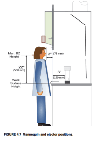
The situations described below involve fumes being detected in labs. This scenario is frequently discovered or verified with the ASHRAE 110 containment test. A complete description of this test is beyond the scope of this paper, but it can be summarized as diffusing a tracer gas, usually sulfur hexafluoride (SF6), into a fume hood. A sensor is placed in the breathing zone of a mannequin 3” past the hood sash plane. If SF6 is detected in the mannequin breathing zone at a concentration at or above 0.050 ppm, the tester and colleagues start looking for things that may be adversely affecting fume hood containment.
1. Some early hood designs would release contained fumes because fumes would get trapped between sash glass and bypass when the sash was raised. This is just one of many examples.
2. Duct leaks, debris in ductwork, broken fan belt, and stuck VAV dampers are some examples.
Examples:
This paper will look at six “case studies” chosen from a lifetime of lab experiences. From these examples, I will suggest a procedure for “fixing” field problems with containment that frequently occur. Each case study is a specific example of the corresponding category on the chart which follows the six examples.
1. Exhaust Fan will not operate.
Once, during a vacation break at a university, I was attempting to field test fume hoods for containment but could not turn the units on. The hoods had no individual “on-off” switches. I was left trying to stare at yet-to-be labeled circuit breakers, one or more of which activated the hoods. I finally discovered the fans were “three phase” units requiring electric three-point relays connect all three hot leads to the fan at once. Once these relay switches were found and made operable, the fans started. This experience taught me that anyone assigned to test construction site exhaust systems in the field should pre-arrange to have a building superintendent present to get things running. It is no fun to have to return to a job site a second day because nobody familiar with the system was there to turn the complex exhaust system on during the first visit!
2. Unexpected corrosion in a fume hood producing no other telltale symptoms.
Many years ago, an oil exploration firm was beginning research work in a new lab complete with new hoods. It was the very first VAV (variable air volume) set-up I had ever seen. Although the lab was full of fume hoods, it was surprisingly quiet due to the VAV system’s automated reduction in flow rate. Not to mention, I didn’t smell anything bad!
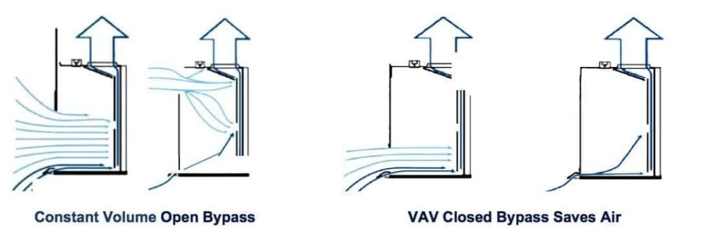
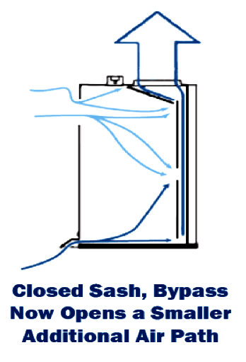
I noticed that, by design, the hoods had no bypasses at the superstructure top. These bypasses were common in the hood industry at this time because it allowed constant volume systems to open an alternate air route into the hood cavity at the top of the unit while closing the sash. This feature mitigated large face velocity increases when one closed the hood sash. But this was a VAV hood. It reduced exhaust air intake as the sash closed, eliminating the need for a bypass. Therefore, contaminant fumes were exhausted using a lower volume of air. The constant volume bypass system, and a VAV alternate, are illustrated below:
The closed bypass hood and damper system worked remarkably well. When I tested the face velocity, it remained constant until the only remaining opening was the 1” airfoil slot.
100 feet per minute (FPM) all the way down. (Remember, this is an early system!)
Yet all the stainless steel equipment inside the hood appeared to be turning rust-red after less than two weeks use. The only application these hoods were being used for was digesting limestone in small watch glasses on hot plates with 20% hydrochloric acid. Most of the time during this procedure, the sash was closed.
We calculated 49 cubic feet per minute (CFM) as the total hood exhaust during closed sash operation (all through the bottom air foil slot). This exhaust was equivalent to about 1 air change per minute (ACPM). This rate was not enough to ventilate the hydrochloric acid vapor from the hood interior, which resulted in corrosion. After further experimentation, we determined that approximately 5 air changes per minute (ACPM) was required to prevent this issue. Since the 1” airfoil was yielding 1 ACPM, we opened 4” of bypass to get 5 ACPM and…no more corrosion! There has been, since 1987, additional ways to assure VAV systems provide minimum air changes. This is also beyond the scope of this paper, but very important to hood safety and product usefulness. With acids and flammable vapors, corrosion and explosion are typically unfavorable consequences of very low minimum air changes.
See the diagram below showing how this early VAV corrosion issue was sorted:
3. Fumes escape from fume hood during raising or lowering of the sash.
While a poorly designed constant volume fume hood can lose containment during a rapid sash movement, several well–designed VAV systems with insufficient maintenance can show the same symptoms. With these VAV systems, the problem is most frequently caused by delay in measuring a condition or a delay in responding to the condition by control elements. Accordingly, the source of the issue is the functionality of the face velocity sensor(s) or damper systems which should appropriately respond to the sensors’ output.
a. Face velocity sensors are usually measuring air flow into the hood through a side-wall sensor or under-airfoil sensor and are most frequently driven by thermistors or hot-wire technology. A few designs measure sash position and infer face velocity using an algorithm and velocity pressure readings in the ductwork (two separate sensors for this example). If these sensors develop changes in sensitivity or fail, slow response to sash changes or worse may occur. Sensor deterioration or failure can be prevented through a rigorous preventative maintenance program.
b. Damper systems require physical movement to execute increases or decreases in exhaust volume. Older damper systems can slow down for a variety of reasons including actuator wear or rotator shaft wear/corrosion. Again, such mechanical depletion or failure can be guarded against through a rigorous preventative maintenance program.
c. Another less frequent cause of slow VAV sash response is the use of VAV sensors to control fan motor rotations per minute (RPM), rather than damper position. This type of system control requires fans to rapidly change RPM when throughput demand changes. Since fans usually have a significant angular momentum, RPM changes are inherently slower to achieve than damper volumetric control.
In any of the above cases, ASHRAE 110-2016 Section 6 outlines measurement methodologies and meaning of sash response time. While the range of acceptable response times is not universally agreed upon, ANSI/AIHA Z 9.5 suggests this time should be < 3 seconds (section 6.3.4.2).
4. While there are no duct leaks or breaches, all building spaces are showing the presence of tracer gas once any hood is operated.
I saw this situation at a rural facility in Texas with about five newly installed fume hoods. All aspects of the hoods appeared normal, except tracer gas during the ASHRAE test showed up everywhere in the building, even in the office area. We asked where the make-up air intakes for the building were located and were told all air was brought in by a single super-intake on the leeward side of the building. We also did smoke tests and watched exhaust air leaving the building through rather short stacks, skimming along the roof line, then diving over the building edge and into the super air intake. Once the intake was disabled, each hood performed normally. At the end of the day, we realized that the problem’s resolution lied within rectification of the intake system. It was either that or making the exhaust stacks taller.
5. All facility fume hoods exhibit very low face velocities. (usually seen where commissioning has not yet taken place)
A new facility with about a dozen fume hoods showed low exhaust face velocities in all the hoods. We were amazed at the consistency of the poor results because there were three separate exhaust fans involved. We finally went to the roof again and asked that the fans be turned off and “bumped”. Bumping a 3 phase fan means asking that they be given a quick “jolt” of power so the direction of rotation can be observed. In each case, the fans were running backwards. A centrifugal fan will always pull air in the correct direction, but will be less efficient if it is run backwards. Once this situation was corrected, the fans all ran at their proper exhaust level and the hood face velocities were normal.
6. Absolutely nothing appears to be wrong with the exhaust system or hood face velocity, but fumes from the hood are showing up in the lab after about one minute!
A new facility perchloric acid hood with good face velocity ran well for about 90 seconds, then the mannequin SF6 detector started showing significant tracer gas. When checked separately, this condition existed in the entire lab. SF6 also was present in neighboring labs on the same floor.
Time for a trip to the building roof.
We found that a decorative skirt had been placed around an unsightly group of “roof penetrations” to make the roof line more attractive. Inside of the skirted area were the perchloric stack and an air intake for the same lab floor. We powered down this air intake temporarily and the hood containment test was successful. We advised the building superintendent to rectify this situation. More often than not such re-entrainment problems are very common, and an additional reason to do ASHRAE 110 field tests.
Summary:
The examples above are, in one form of another, very common reasons for fume hood systems “not working”. The entire picture of design flaws, maintenance issues, or aesthetics-functionality conflicts is obviously more complex and more details can be reviewed further in the following papers on the Flow Sciences website:
- How Should VAV Equipment Be Specified on Laboratory Hoods?
- The Feasibility of Fume Hood Containment at 40 FPM.
- VAV Energy Savings at High and Low Face Velocities.
- The Overlapping Sash Bypass System
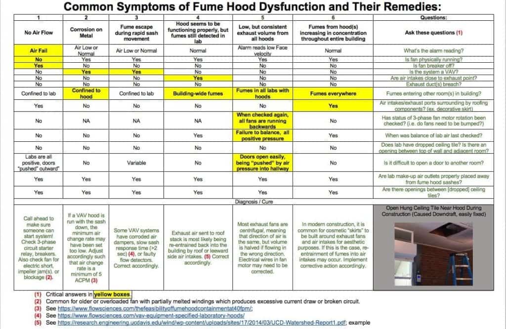
The Chart:
The Summary Chart below shows six primary containment issues that probably could represent the “80” in the 80/20 rule for fume hoods. Both the fourteen questions and six diagnoses should help building designers and project managers determine good design techniques and “tells” usually present when things do not go according to plan!
The author invites any comments on this paper and chart as additional experience will always make an experiential summary more robust!